Category:BOB Constructional Sets (Rob Toys)
| Toy Brands and Manufacturers |
|---|
BOB Constructional Sets (Rob Toys) |
| 1946 - |
1937 patent figure, Charles Henry Baumgartner [image info]
BOB joints, Figure 1 [image info]
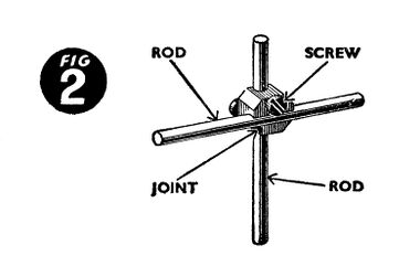
BOB joints, Figure 2 [image info]
BOB joints, Figure 3 [image info]
BOB joints, Figure 4 [image info]
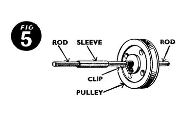
BOB joints, Figure 5 [image info]
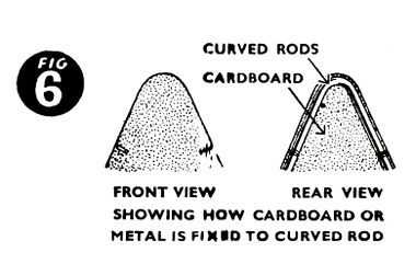
BOB joints, Figure 6 [image info]
The BOB Construction Toy system was a metal construction toy based around rods and screw-fixed jointing pieces, that fitted together in a manner reminiscent of scaffolding poles and joints.
Dates
The manual that we have mentions an expansion of the range expected in 1947, which suggests that the manual was probably printed in 1946 (i.e. just after World War Two, 1939-1945).
The system itself had a patent applied for back in 1937, which was granted in 1939. We don't currently know if the system was ever manufactured in the 1930s ... if not, it would seem that its launch (or its UK launch) might have been held back by the outbreak of the Second World War.
Inventor
The 1937/39 patent (500629) was applied for by Charles Henry Baumgartner, a Swiss citizen, of Pinchat, Geneva.
Manual text:
ENGINEERING is the key to all the comforts and conveniences of modern life.
In 1785 the first locomotive ran at 12 m.p.h. and the world hailed it as a triumph of mechanical skill. Today, more than 100 m.p.h. faster has been run by the famous British "Silver Jubilee"; that is just one result of skilled and thorough engineering practice.
You belong to the modern world – the mechanised world; it is up to you to know all you can about it. Perhaps, too, you have the hidden genius of a great engineer in your brain and hands; let BOB help you to find out.
BOB is a grand hobby, a fascinating occupation and may open the doors of your career in life.
Now to work. Study the instructions carefully before you start; thoroughness is one of the most important qualities in an engineer. Imagine that the models you make are miniatures of things actually to be used – things that must not fail in use. That is the way to get the best out of your BOB kit. Ask a friend to join you – between you many other ideas and designs will come besides those shown in the manual. Try to create new models; the great engineer is a creative designer, and you must train your brain to produce original ideas.
Write to us if you are in doubt or if you would like to make original suggestions; the BOB engineers will welcome your letter and are ready to help in any way they can.
Instructions
When you first open your BOB Set, do not at once remove the parts, study them on the card for a time, and become familiar with them. Get to know what each part looks like, its name, and its purpose. An engineer is always familiar with the materials with which he works, and YOU are learning to be an engineer.
Now study all the fascinating things shown on pages 10, 12 and 14 which can be made from BOB Sets. Consider their detail and construction and then get to work.
After a little practical experience with your BOB parts you will be able to make not only the models illustrated but your own too – bridges, aeroplanes, etc. and many other novel assemblies. But remember, see the model in your mind's eye before you start constructing, better still make an actual drawing of it. With BOB you are building to scale and anything you create will be like the Real Thing in miniature.
Explanation of BOB Parts
The different parts required for all assemblies are limited to 5, viz., joints, rods, sleeves, pulleys and clips.
1. Special union joints with 2 grooves in which a rod is held by the pressure of a screw head. 2. Steel rods 3 mm. in diameter and 25 to 250 mm. in length. 3. Sleeves which make it possible to obtain instantly rods of any required length by joining them end to end. 4. Pulleys which can also be used as wheels when constructing vehicular models. 5. Clips to secure wheels, pulleys and other parts.
BOB needs only one tool – THE SCREWDRIVER.
How to assemble BOB parts
To get the rod into the groove of the joint all you have to do is:
Loosen the screws by 1½ to 2 turns (supposing it was screwed up tight in the beginning) so that the rod can be pushed in from the end. Fix the position of the joint by measurement with your ruler before tightening screw.
Always take care to allow play between wheel and clip in order that the wheels may rotate freely.
Panelling
Once the framework of a model has been put together, it can be made to look more finished (seat, bed, windmill, tramcar, aeroplane, etc.) by placing on it panels of cardboard or metal of suitable size and colour.
It is easy to imagine the way panels are fixed to the rods. One of the most suitable and effective means is to use a rivet which passes through the panel and is held in the joint, together with the rod as shown in diagram at back of your BOB cover.
Later BOB sets, ready in the near future, will include panels for this purpose. These you will find ideal in many ways. Details, however, will be explained to you when the time comes.
Whatever method is applied be sure to make a good job. Neatness is essential – your reward will be a faithful reproduction of the Real Thing.
Presentation of BOB
For the present BOB is supplied in 3 Sets, Numbers 0, 1 and 2 with Supplementary Sets Number 0A and 1A as listed on pages 3 to 5. The larger Set will in each case make all the models listed for any lower numbered set.
The main sets are boxed and fitted with Screwdriver and Rule. The Supplementary Sets are only carded as there will be room in your box to keep the extra parts.
In addition to this, separate parts can be purchased as required so as to meet the needs of your own ideas.
Once a model using all the parts of a box has been assembled you are certain to want more.
Prices and particulars of additional parts may be had from your local supplier.
In case of difficulty or if supplier is out of stock, write to: RIDINGBERY & CO., LTD., BOB Dept., Feeder Road, Bristol 2. stating the name and address of your nearest toy shop.
SET CONTENTS
all part numbers start with "1997/"
CONTENTS OF No. 0 SET
Will make 40 models, part of which are illustrated on page 10.
- 45 – 25mm. Rod – × 4
- 44 – 50mm. Rod – × 5
- 43 – 75mm. Rod – × 5
- 42 – 100mm. Rod – × 4
- 20 – 150mm. Rod – × 3
- 46 – 100mm. Rod, Curved – × 2
- 22 – Joint Casting – × 6
- 21 – Joint Screw – × 12
- 24 – Clip – × 5
- 49 – Sleeve ... – × 2
- 47 – Hub Pulley, 30mm. diameter – × 1
- 33 – Pulley, Plain 18mm. diameter – × 1
- 23 – Pulley, Plain, 30mm. diameter – × 2
- 48 – Rivet – × 2
- Metric Rule, 300mm. – × 1
- Screw Driver – × 1
- Skein of Twine – × 3ft.
CONTENTS OF SUPPLEMENTARY SET No. OA
By adding the above parts, your No. 0 Set becomes No. 1, enabling you to make at least 80 models. Part of the additional models are illustrated on page 12.
- 45 – 25mm. Rod – × 2
- 43 – 75mm. Rod – × 3
- 42 – 100mm. Rod – × 2
- 20 – 150mm. Rod – × 4
- 22 – Joint – × 6
- 21 – Joint Screw – × 12
- 49 – Sleeve – × 2
- 52 – Crank, 50mm. – × 1
- 53 – Pulley with Perforated Face, 30mm. diameter – × 4
CONTENTS OF No. 1 SET
Will make 80 models, part of which are illustrated on page 12.
- 45 – 25mm. Rod – × 6
- 44 – 50mm. Rod – × 5
- 43 – 75mm. Rod – × 8
- 42 – 100mm. Rod – × 6
- 20 – 150mm. Rod – × 7
- 46 – 100mm. Rod, Curved – × 2
- 22 – Joint Casting – × 12
- 21 – Joint Screw – × 24
- 24 – Clip – × 5
- 49 – Sleeve – × 4
- 47 – Hub Pulley 30mm. diameter 1
- 33 – Pulley, Plain 18mm. diameter – × 1
- 23 – Pulley, Plain, 30mm. diameter – × 2
- 48 – Rivet – × 2
- 53 – Pulley with Perforated Face, 30mm. diameter – × 4
- 52 – Crank, 50mm. – × 1
- 54 – Pulley with Perforated Face, 20mm diameter – × 1
- 57 – Crank, 100mm – × 1
- Metric Rule, 300mm.
- Screw Driver
- Skein of Twine – × 3ft.
CONTENTS OF SUPPLEMENTARY SET No. 1A
By adding the above parts your No. 1 Set becomes No. 2, enabling you to make at least 120 models, part of the additional models are illustrated on page 14.
- 45 – 25mm. Rod – × 8
- 44 – 50mm. Rod – × 4
- 43 – 75mm. Rod – × 4
- 42 – 100mm. Rod – × 4
- 18 – 200mm. Rod – × 8
- 16 – 250mm. Rod – × 10
- 22 – Joint – × 12
- 21 – Joint Screw – × 24
- 24 – Clip – × 4
- 49 – Sleeve – × 11
- 33 – Pulley, 18mm. diameter – × 2
- 53 – Pulley with Perforated Face, 30mm. diameter – × 2
- 54 – Pulley with Perforated Face, 20mm. diameter – × 6
- 57 – Crank, 100mm. – × 1
CONTENTS OF No. 2 SET
Will make 120 models, part of which are illustrated on pages 10, 12 and 14.
- 45 – 25mm. Rod – × 14
- 44 – 50mm. Rod – × 9
- 43 – 75mm. Rod – × 12
- 42 – 100mm. Rod – × 10
- 20 – 150mm. Rod – × 7
- 18 – 200mm. Rod – × 8
- 16 – 250mm. Rod – × 10
- 46 – 100mm. Rod, Curved – × 2
- 22 – Joint Casting – × 24
- 21 – Joint Screw – × 48
- 24 – Clip – × 9
- 49 – Sleeve – × 15
- 47 – Hub Pulley, 30mm. diameter – × 1
- 33 – Pulley, Plain 18mm. diameter – × 3
- 23 – Pulley, Plain, 30mm. diameter – × 2
- 48 – Rivet – × 2
- 53 – Pulley with Perforated Face, 30mm. diameter – × 6
- 52 – Crank, 50mm. – × 1
- 54 – Pulley with Perforated Face, 20mm. diameter – × 6
- 57 – Crank, 100 mm – × 1
- Metric Rule, 300mm. – × 1
- Screw Driver – × 1
- Skein of Twine – × 3-ft.
So far 3 BOB Sets are on Sale, Nos. 0, 1 and 2, together with Supplementary Sets 0A and 1A.
In 1947 further BOB Sets will be ready for you which will make an entirely new range of models in addition to the existing ones. It is in your own interests to look after all your pieces very carefully – as this will allow you to build some other splendid models which will appear later in a supplementary booklet.
Addresses
- RIDINGBERY & CO., LTD. – BOB Dept., Feeder Road, Bristol 2.
Patents
Pages in category ‘BOB Constructional Sets (Rob Toys)’
This category contains only the following page.
Media in category ‘BOB Constructional Sets (Rob Toys)’
The following 12 files are in this category, out of 12 total.
- BOB Construction Sets (Patent GB 500629 A.jpg 1,501 × 2,400; 585 KB
- Box lid (Bob Kit No-0).jpg 2,200 × 1,392; 648 KB
- Figure 1, BOB Construction Kits (RobToys).jpg 1,560 × 1,030; 167 KB
- Figure 2, BOB Construction Kits (RobToys).jpg 1,560 × 1,030; 180 KB
- Figure 3, BOB Construction Kits (RobToys).jpg 1,560 × 1,030; 292 KB
- Figure 4, BOB Construction Kits (RobToys).jpg 1,560 × 1,030; 157 KB
- Figure 5, BOB Construction Kits (RobToys).jpg 1,560 × 1,030; 199 KB
- Figure 6, BOB Construction Kits (RobToys).jpg 1,560 × 1,030; 354 KB
- Instructions, cover (BOBKit ~1946).jpg 2,200 × 1,702; 790 KB
- Label from inside box lid, (Bob Kit No-0).jpg 2,200 × 1,450; 740 KB
- Rob Toys logo, colour.jpg 732 × 697; 454 KB
- Rob Toys logo, mono.jpg 554 × 604; 156 KB


